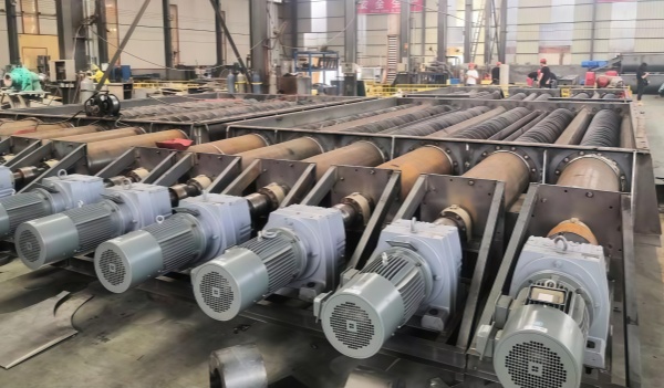
Live Bottom Screw Conveyor Machine Manufacturer
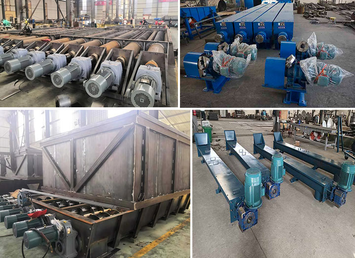
The Live Bottom Screw Conveyor Machine is a heavy-duty discharge device installed at the bottom of silos and hoppers. It utilizes multiple parallel screw shafts covering the entire outlet cross-section to achieve continuous withdrawal and quantitative feeding of high-viscosity, sticky, and cohesive materials.
- Discharge Capacity: 5 m³/h – 200 m³/h
- Screw Shaft Quantity: 2, 3, 4, 6 or Custom Shafts
- Screw Diameter Range: 200 mm – 600 mm
- Trough & Flight Material: Carbon Steel / SUS304 / SUS316L / NM400 Wear Plate
- Drive Setup: Individual or Coupled Heavy-Duty Gearmotors with VFD
Due to the compression of wet materials, bridging, clumping, and dead spots frequently occur at the bottom of silos, causing single-shaft feeding equipment below to idle without discharging material. The Live Bottom Screw Conveyor Machine features multiple parallel screw shafts arranged at the hopper bottom to form a live-bottom discharging structure, forcefully shearing material clumps and breaking internal stress. The system operates at the bottom of large-area rectangular hoppers, square silos, and flat-bottom collection box outlets. Handled materials include dewatered sludge, biomass wood chips, wet bark, clay, desulfurization gypsum, wet ash, and high-viscosity wet powders, covering bulk densities from 0.3 t/m³ to 1.8 t/m³. Troughs and screws can be fabricated from Q235B carbon steel, SUS304/SUS316L stainless steel, or welded with NM400 wear-resistant layers on flight edges. The conveying capacity is controlled between 5 and 200 cubic meters per hour.
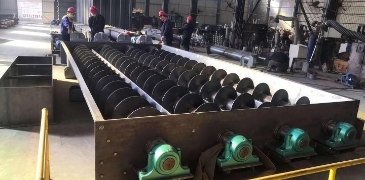
Technical Specifications of Live Bottom Screw Conveyor Machine
| Parameter | Specification / Range | Engineering Detail |
| Discharge Capacity | 5 m³/h – 200 m³/h | Calculated based on bulk density 0.8 t/m³ |
| Number of Screws | 2, 3, 4, 6 Shafts | Full trough bottom coverage design |
| Screw Shaft Type | Shafted or Shaftless | Shaftless type for sticky, fibrous material |
| Screw Diameter | 200 mm – 600 mm | Pitch-to-diameter ratio 0.5–1.0 |
| Main Motor Power | 5.5 kW – 75 kW per drive | High torque gear reducer with VFD support |
| Bearing Location | Outboard Heavy-Duty Block Bearings | External flange seal prevents fluid leakage |
Working Principle: Arch-Breaking & Live Bottom Metering
The operation of the Live Bottom Screw Conveyor Machine is based on physical mechanisms of multi-shaft synchronized forced propulsion, shearing, and compression. Material inside the silo settles under gravity into the multi-screw bottom region, where multiple live bottom screws arranged in parallel rotate co-directionally or in opposite directions. This generates continuous shear forces on the accumulated material at the hopper bottom, disrupting the physical conditions that cause material particles to clump into arches.
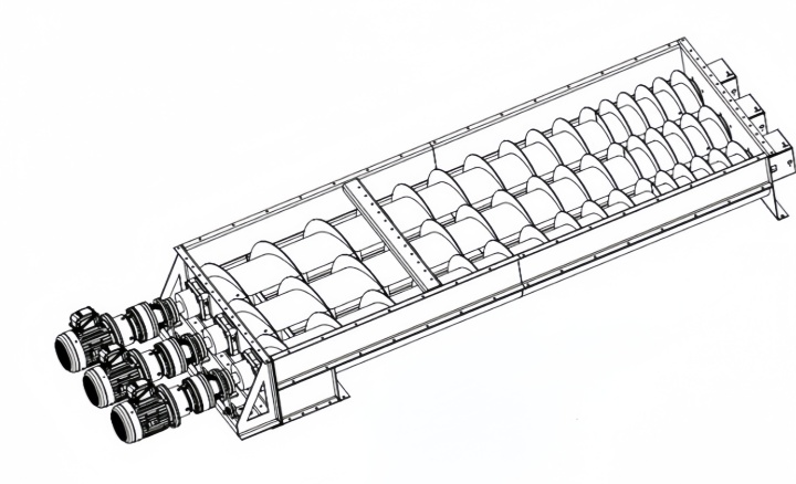
The screw design employs a variable pitch configuration, featuring smaller pitch at the inlet end and gradually larger pitch toward the outlet end. This prevents local compression and overload at the front of the discharge port, ensuring equal-volume material extraction along the entire length of the hopper bottom opening. Functioning as a live bottom material meter, the drive system is integrated with a variable frequency drive (VFD) to fine-tune motor rotation speed, translating screw revolutions into physical discharge volume and delivering a steady material stream to downstream processing stages.
Live Bottom Conveyor vs. Standard Screw Conveyor
| Structural Feature | Live Bottom Conveyor | Standard Screw Conveyor |
| Inlet Section Area | Full hopper bottom opening coverage | Small circular or rectangular inlet |
| Arch-Breaking Ability | Multi-shaft active shear prevents bridging | No anti-bridging capability |
| Screw Quantity | 2 to 6 parallel live bottom screw feeders | Single shaft or standard twin shafts |
| Flight Pitch Profile | Variable pitch along the feed zone | Fixed pitch throughout the trough |
| Bearing Placement | Outboard bearings separated from material | End bearings close to material trough |
| System Classification | Heavy-duty live bottom conveyor discharger | Linear live bottom transport unit |
Manufacturing Quality & Heavy-Duty Structural Options
The drive end of the equipment is configured with multiple individual motor drives or a single motor paired with a distribution gear drive system. The reducers utilize helical hard-toothed gears capable of delivering output torques exceeding 5000 N·m, supporting cold starts under full-load static pressure within the silo.
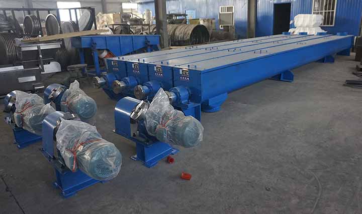
The trough side plate thickness is set from 8 mm to 12 mm, with 10 mm thick NM400 wear-resistant liners fitted at the bottom. Heavy-duty outboard pillow block bearings are selected for the shaft ends, and gland packing seals with pre-installed air or fluid purging ports are fitted inside the seal housing to isolate corrosive liquids or hard dust particles outside the bearing housings.
Applications & Industrial Solutions
The equipment operates in dewatered sludge storage and cake conveying lines at wastewater treatment plants, bark and wood chip co-firing feeding systems at biomass power plants, fly ash stabilization units at waste incineration facilities, and high-viscosity wet powder batching control operations in chemical plants. In automated feeding conditions as a live bottom conveyor discharge unit, the equipment works alongside level sensors and load cells to execute quantitative discharge, reducing downtime and manual clearing frequencies caused by silo blockages.
Frequently Asked Questions
Q: How does a live bottom screw conveyor prevent material bridging in the storage hopper?
Multiple screws span horizontally across the full hopper bottom outlet, eliminating stagnant material dead zones. The physical shearing action generated by the rotating screws directly breaks the internal stress structure of the material. Combined with the variable pitch design in the inlet zone, this causes material to settle and discharge uniformly across the full length of the hopper bottom, preventing the formation of arch structures that support the weight of the material above.
Q: What is the primary difference between live bottom screw feeders and a standard twin screw conveyor?
Standard twin screw conveyors are primarily used for parallel mixing and short-distance transport of materials within a trough, featuring relatively small inlet dimensions. In contrast, live bottom screw feeders comprise 2 to 6 or more screws that directly form the hopper bottom structure, focusing on breaking material bridging inside the silo and accomplishing large-area uniform material extraction.
Q: Why are outboard bearings necessary for live bottom conveyor systems?
Material at the silo bottom is subjected to massive static pressures and is often accompanied by leachate or abrasive dusts. Positioning the bearing housings externally away from the trough end plates allows leaking material to drop directly into the atmosphere if a seal fails, preventing contaminants from entering the bearing raceways and causing jamming or accelerated wear.
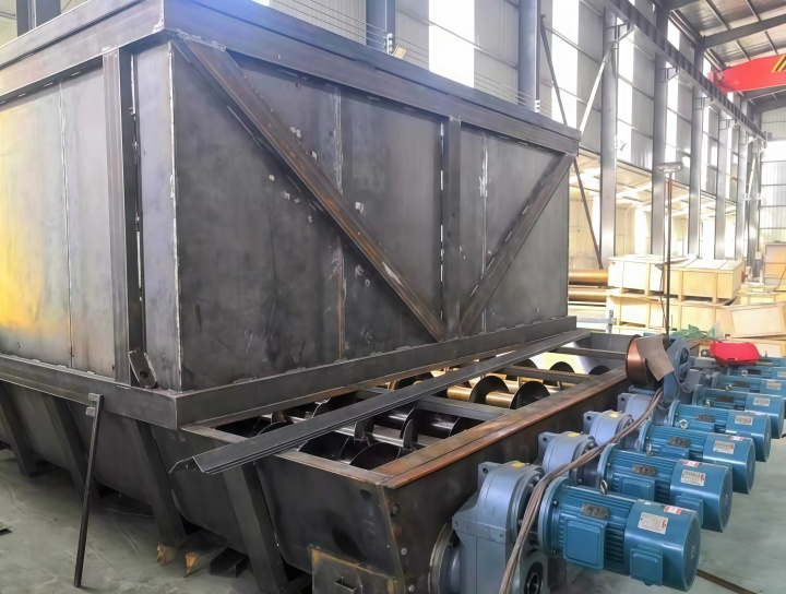
The Live Bottom Screw Conveyor Machine utilizes a multi-screw parallel structure and variable pitch design at the hopper bottom to provide physical shearing and steady-flow discharge solutions for high-viscosity, bridge-prone materials. High-torque reducer output paired with outboard bearing seal configurations adapts to full-load starting and highly abrasive operating conditions. Available in custom 2-shaft to 6-shaft specifications with carbon steel, stainless steel, or NM400 wear plate materials, it achieves continuous quantitative discharging from 5 to 200 cubic meters per hour, reducing maintenance and shutdown frequencies.
Sugested Products
High Temperature Screw Conveyor
Twin Screw Mixer
Sludge Screw Conveyor
Garbage screw conveyor