Common Weighing Errors in Weighing and Batching System and How to Fix Them
Monday September-07 2026 13:48:25
Most accuracy issues in a Weighing and Batching System can be traced back to three sources: mechanical interference, control logic flaws, and signal noise contamination. A building materials plant once experienced a 0.5 kg daily drift in empty-load readings, resulting in continuous out-of-spec batches. After replacing the sensor three times with no improvement, the root cause turned out to be a hard pipe connection to the hopper—a hidden problem that occurs frequently on production floors.
A weighing and batching system faces far more challenges in real-world conditions than under static laboratory settings. Pipe rigidity, equipment vibration, temperature fluctuations, electrical noise, and variations in material properties all continuously degrade measurement accuracy. This article examines six common types of weighing errors in it, analyzes their root causes, and provides actionable solutions with specific operating parameters and verification metrics.
Weighing and Batching System Error 1: Measurement Deviation from Mechanical Constraints
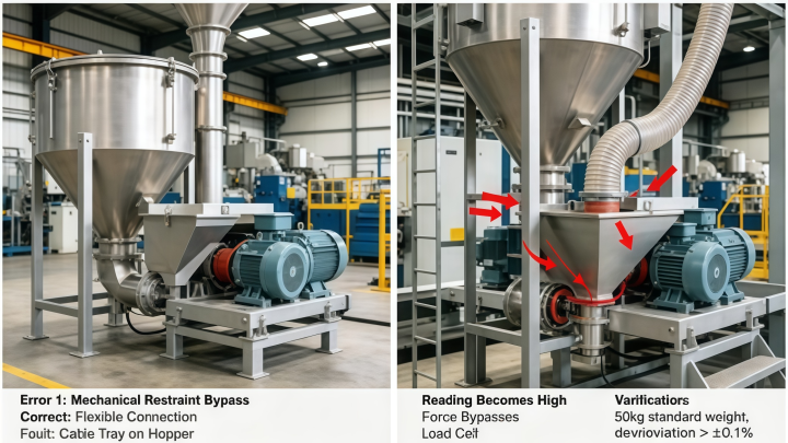
A more concealed error source is force bypass through mechanical structures. When the weighing hopper contacts pipes, platforms, or building structures, external forces bypass the load cells and transmit directly, causing distorted readings. At one site, readings consistently drifted high after each startup. Investigation revealed that the cable tray rested directly on the hopper—removing it eliminated the issue immediately.
Check each connection point systematically: feed pipes must use flexible connectors, discharge mechanisms should not make rigid contact with fixed structures, and no cables or air lines should rest on weighing structures. Newly installed equipment requires hot-state inspection of pipe expansion effects.
Verification metric: apply a 50 kg standard test weight under empty-load conditions. If the reading deviates by more than ±0.1%, force bypass in the mechanical path is confirmed.
Weighing and Batching System Error 2: Accuracy Loss from Calibration and Zero Drift
Calibration deviation is a common accuracy problem. A single calibration does not maintain long-term accuracy—zero points shift over time with temperature changes and sensor creep. Typical signs include non-zero empty-load readings, increasing deviation in test weight verification, or loss of accuracy within days after calibration.
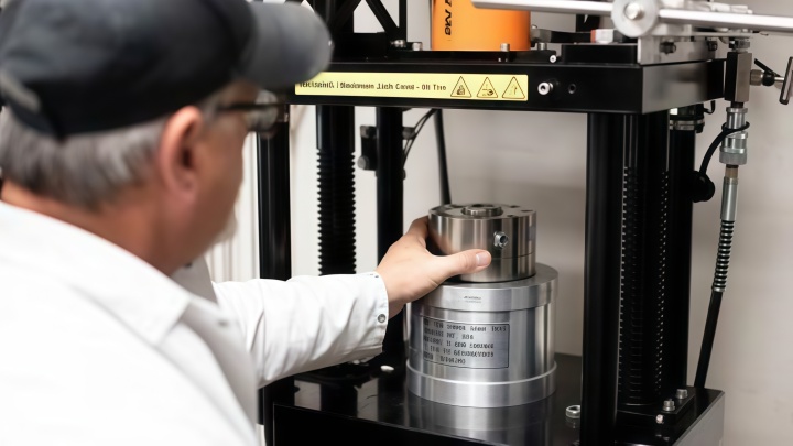
Implement a periodic calibration schedule: zero calibration weekly and span calibration monthly. Allow at least 30 to 60 minutes of warm-up before each calibration. After calibration, verify with standard test weights at four points: 20%, 50%, 75%, and 100% of full scale.
If repeated calibration fails to stabilize the system, measure the sensor output in millivolts with a multimeter and check for internal strain gauge damage or signal line contact resistance exceeding 5 ohms.
Weighing and Batching System Error 3: Batch Deviation from In-Flight Material and Dynamic Effects
At the instant the feed valve closes, material still in suspension within the pipe continues to fall into the container—this in-flight material is a common error source. Without compensation, each batch shows systematic deviation, typically 0.3% to 1.5% of the target weight, varying with material flowability, pipe length, and feed rate.
Set a pre-close offset in the control program: based on material drop time statistics, close the valve 50 to 200 milliseconds before the target weight is reached. The specific value should be determined through actual measurement of pipe length and material flow rate. For higher-accuracy requirements, use a two-stage feed strategy: coarse feed delivers 90% to 95% of the total, then switch to slow fine feed to minimize in-flight material effects.
Re-measure drop time and update compensation parameters with each material batch change.
Weighing and Batching System Error 4: Measurement Stability Interference from Environmental Vibration
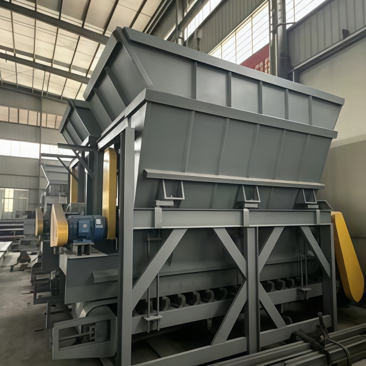
Vibration from crushers, compressors, fans, and material conveyors transmits through structures to the load cells and is recorded as actual weight change. This interference appears as continuous fluctuation with unstable readings, typically at frequencies between 10 and 100 Hz.
For hardware solutions, install equipment away from vibration sources and isolate the hopper from foundations using isolator pads with compression deformation below 5% or dedicated weighing modules. For software solutions, use the built-in digital filtering function: set time constants between 0.5 and 2 seconds and cutoff frequencies between 5 and 15 Hz to filter high-frequency vibration while maintaining normal response speed.
Note that every 0.5-second increase in filter time constant adds approximately one sampling period to system response lag—find the right balance between stability and response speed.
Weighing and Batching System Error 5: Zero Offset from Material Build-Up and Hang-Up
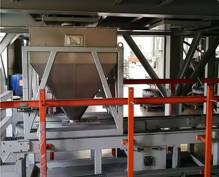
Material adhesion on the inner walls of the weighing container is an easily overlooked cumulative error source. Powdery or moist materials accumulate layer by layer on hopper walls, adding 0.2% to 2% of sensor capacity. This weight is continuously recorded by the sensor but never contributes to the formula output, causing the empty-load zero point to shift systematically.
Include cleaning in every shift maintenance: clean the inner walls every four to eight hours of operation and confirm that the indicator returns to zero reliably within ten seconds after each discharge. For sticky materials, install pneumatic hammers or vibrators to aid discharge, with vibration frequency at 20 to 30 Hz, 3 to 5 seconds per cycle, and intensity that does not compact the material.
Perform an empty-load zero check before each shift startup—if the reading deviates by more than 0.05% of sensor capacity, clean immediately.
Weighing and Batching System Error 6: Weak Signal Contamination from Electrical Interference
Load cell output signals are weak—typically between 0 and 30 millivolts. When signal cables run in parallel close to VFDs, motor leads, or high-current lines, electromagnetic fields induce noise up to 5% to 20% of the signal amplitude. This interference appears as irregular fluctuations correlated with the start-stop cycles of nearby high-power equipment.
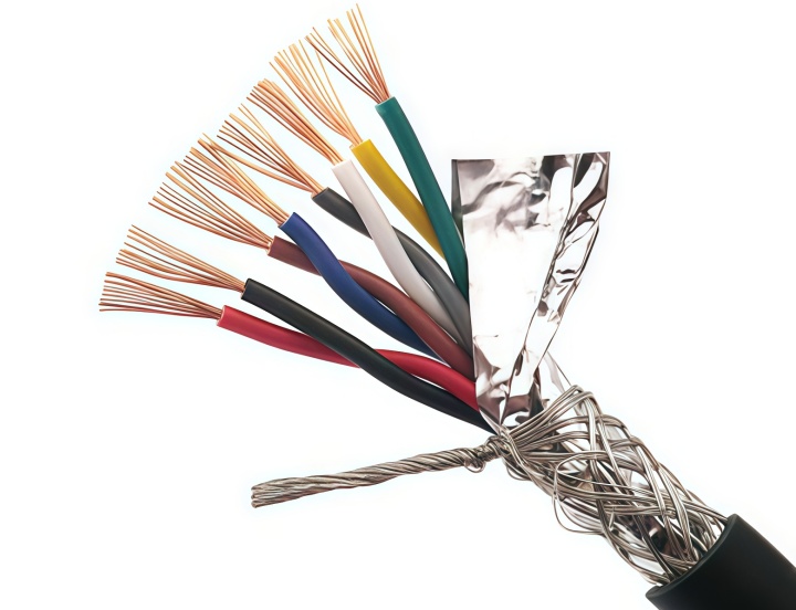
Follow proper wiring practices: separate signal cables from power cables with a minimum distance of 300 mm, and cross at 90-degree angles where necessary. Use twisted-pair shielded cables with the shield grounded at a single point on the instrument end and ground resistance below 4 ohms. Inspect junction boxes monthly for moisture intrusion, loose terminals, and corrosion.
For severe interference environments, switch from 4-20 mA analog signal transmission to RS485 digital communication to improve noise immunity significantly.
Weighing and Batching System Troubleshooting Quick Reference Table
| Error Type | Typical Symptoms | Priority Inspection Areas | Quantitative Verification Metric |
|---|---|---|---|
| Mechanical Constraint | Readings change when people move nearby; no zero return empty | Pipe flex connectors; structural contact points | 50kg test weight deviation exceeds ±0.1% |
| Calibration Drift | Empty display not zero; test weight deviation persists | Multi-point calibration; sensor signal lines | Error exceeds ±0.05% at any of 4 span points |
| In-Flight Material | Systematic batch weight deviation high or low | Pre-close offset; coarse/fine feed switch point | Batch deviation persists above 0.3% of target |
| Environmental Vibration | Continuous fluctuation; unable to lock stable reading | Isolation mounting; digital filter settings | Vibration 10-100Hz with fluctuation >0.1% |
| Material Hang-Up | No zero return after discharge; poor batch consistency | Container wall cleaning; discharge assistance | Zero offset exceeds 0.05% of sensor capacity |
| Electrical Interference | Irregular fluctuation correlated with high-power equipment start/stop | Signal-power separation; shielded grounding | Signal noise exceeds 5% of signal value |
Weighing and Batching System Frequently Asked Questions
Why does my weighing and batching system take longer to complete each cycle?
Overly conservative feed parameter settings are a common cause of extended cycle times. Check the coarse-to-fine feed switch point and delay the switch appropriately to reduce single-batch duration.
What should I do when material blocks the weighing and batching system?
Bridging or arching in the hopper interrupts material flow. Install flow aids such as pneumatic hammers or vibrators and clean hopper wall accumulations regularly.
How do I fix dust issues in my weighing and batching system?
Dust generated during batching affects both safety and sensor accuracy through surface adhesion. Check all connection seals and install a dust collection system.
Does material moisture variation affect weighing and batching system accuracy?
Yes. Changes in moisture content and bulk density alter flowability, affecting feed rate and final measurement. Recalibrate parameters promptly when material batches change.
When to Involve Professional Technicians
If errors persist after implementing all the above troubleshooting steps, or if load cell replacement, instrument repair, or control logic redesign is required, bring in professional technicians.
Load cell replacement requires recalibration and corner adjustment. Record original values before modifying any instrument parameters to allow rollback. These operations involve system-level configuration and should not be performed by non-specialists, as improper handling may cause more serious accuracy issues or equipment damage.
Closing Remarks
Accuracy issues in a weighing and batching system rarely have a single cause. Check mechanical constraints through hard connections and flexible joints. Validate calibration drift with multi-point verification. Adjust in-flight material with pre-close offset. Address environmental vibration with isolation and filtering. Manage hang-up through regular cleaning. Separate power and signal lines for electrical interference. Each of the six error types has a clear cause and corresponding solution path, and the quick reference table provides quantitative verification metrics to make troubleshooting data-driven.
Regular calibration, proper wiring, structural independence, and recording parameter changes with before-and-after comparisons are the foundational practices that keep the system reliable. The quantitative data and operating parameters in this article are intended to help you identify root causes faster and fix them precisely. For complex situations involving system-level configuration or hardware replacement, consult a professional technical team for targeted support.