Flexible vs Rigid Screw Conveyor: 3 Key Differences Explained
Friday July-17 2026 14:37:27
In the bulk solids handling industry, choosing the right material conveying solution directly affects the energy consumption and discharge stability of the entire production line. Flexible Screw Conveyors typically consist of a shaftless rotating spiral and a flexible Ultra-High-Molecular-Weight Polyethylene (UHMW-PE) tube. On the other hand, Rigid Screw Conveyors are composed of continuous or sectional flights fixed onto a central metal shaft, enclosed within a metal trough or housing. Fundamental differences exist between the two regarding driving methods and material carrying mechanisms. This article provides a deep technical analysis across three dimensions—spatial geometric routing, material physical property compatibility, and daily maintenance versus total operating costs—to deliver data-backed support for engineering equipment selection.
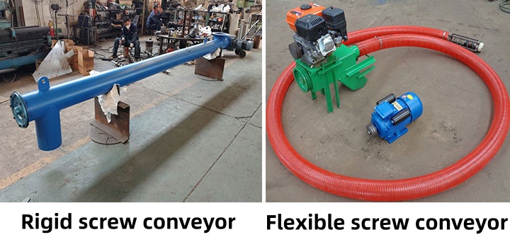
Difference 1: Physical Routing and Spatial Layout
Due to the physical constraints of the central metal shaft and housing material, rigid conveyors can only operate in a single straight line horizontally, vertically, or at a fixed incline angle. When the interior of a plant features structural columns, large equipment obstructions, or requires materials to be conveyed to non-linear intersection points, rigid systems must utilize multiple units arranged in a series relay. Each material transfer point requires an additional drive motor and increases the risk of material degradation and dust emissions at the transition point.
Conversely, flexible conveyors leverage the elasticity of the shaftless spiral, allowing the conveying tube to bend within a certain curvature radius. This design enables them to bypass existing obstacles within the workshop, routing across different floors and wall barriers. By connecting the starting point directly to the destination, it eliminates intermediate transfer hoppers, reduces the chance of material exposure to the air, and is highly applicable to space-constrained or complex workshop environments requiring three-dimensional routing.
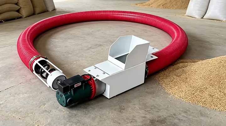
Difference 2: Material Property Compatibility and Handling of Hygroscopic Materials
The internal mechanical performance of these two types of equipment varies drastically when dealing with bulk materials of different physical characteristics:
- Blended Materials and Particle Size Distribution: The central shaft and hanger bearings inside a rigid conveyor can disrupt the flow state of the material. When conveying mixed powders with varying densities and particle sizes, gravitational settling can lead to segregation or de-mixing over long distances. In contrast, the shaftless spiral of a flexible conveyor relies on constant centrifugal force to push the material against the tube wall, keeping the material in a mass-flow state within the tube, which effectively prevents the segregation of multi-component powders and maintains blend uniformity.
- Heavy-Duty and Abrasive Materials: Supported by a high-strength metal central shaft, rigid systems feature metal flights with greater resistance to torsional failure when conveying highly abrasive or high-density large-particle materials such as carbon black, sand, or ores. A flexible spring, however, is prone to elongation deformation or accelerated tube wall wear under such working conditions.
Deep Dive: Handling Mechanisms for Hygroscopic Materials
For hygroscopic materials (such as sugar, salt, and chemical powders) that easily absorb moisture and agglomerate, the performance of the two systems differs distinctly. Flexible conveyors utilize a sealed polyethylene tube that prevents external moisture from entering; during operation, the slight vibration of the flexible spring itself helps dislodge any caked material adhering to the tube wall. Rigid conveyors, when handling such materials, can address agglomeration and adhesion issues by designing a sealed jacket around the outer shell to introduce dry nitrogen or a heating medium, thereby controlling internal temperature and humidity.
Difference 3: Maintenance, Cleaning, and Operating Costs
From a mechanical structure standpoint, when a rigid screw conveyor exceeds a length of 3 to 4 meters, internal hanger bearings must be installed to prevent the central shaft from sagging or deflecting. Hanger bearings are buried in the material for long periods, meaning seals are easily worn down by fine powder, leading to lubricant contamination of the bulk material or material entering the bearing, which causes equipment seizure. Maintenance requires technicians to disassemble the housing and clear out residual material, with downtime typically measured in hours.
Flexible conveyors eliminate internal hanger bearings and end seals, with the only bearing located at the drive end, completely isolated from the material zone. This significantly simplifies the cleaning process. When switching material batches, operators only need to loosen the quick-release couplings and pull out the internal spiral to flush the smooth interior of the polyethylene tube with water or an air gun, reducing downtime to just a few minutes. In terms of energy consumption, because the flexible system reduces mechanical friction points, its baseline power consumption shows clear economic efficiency under equivalent conveying volumes.
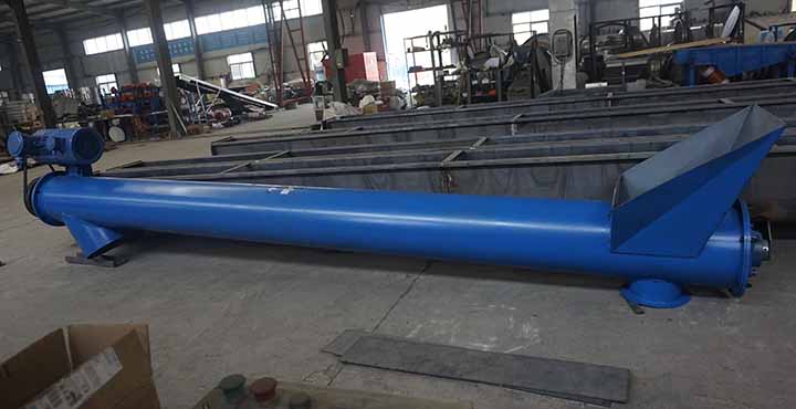
Decision Guide: Which One Should You Choose?
To assist engineering procurement teams in rapid evaluation during selection, a quantitative comparison reference framework has been established based on key process parameters:
| Selection Metrics | Flexible Screw Conveyor | Rigid Screw Conveyor |
|---|---|---|
| Conveying Geometric Path | Allows curved bending, bypassing obstacles, multi-angle shifts | Strictly straight line (horizontal, inclined, or vertical) |
| Internal Support Structure | Shaftless, no internal hanger bearings | Equipped with a solid central shaft; requires hanger bearings for long distances |
| Material Uniformity Retention | Suppresses segregation/de-mixing of multi-component powders | Long-distance conveying easily leads to blend segregation |
| Abrasive Material Suitability | Prone to accelerated wear on the spring and tube wall | Can carry heavy abrasive loads when using wear-resistant alloy flights |
| Typical Single-Unit Conveying Distance | Generally does not exceed 15 meters | Can extend beyond 30 meters using couplings and multiple hanger bearings |
| Material Cleaning & Batch Changeover | Supports quick disassembly with zero dead zones for cleaning | Complex structure with many blind spots; time-consuming to clean |
Alternative Technologies: Beyond the Screw
In the bulk material handling technology landscape, screw conveying technology is frequently compared horizontally with pneumatic conveying technology:
- Flexible Screw Conveyor vs. Pneumatic Conveyor: Pneumatic conveying uses high-pressure airflow or vacuum suction to move materials, making it ideal for large-scale plants with conveying distances exceeding 50 meters. However, pneumatic systems involve high capital costs for gas-solid separators, and high-velocity air streams can easily cause particle breakage (product degradation). Flexible screws advance materials gently through mechanical rotation, consuming a fraction of the power of a pneumatic system while minimizing mechanical damage to fragile particles.
- Flexible Screw Conveyor vs. Conventional Rigid: While traditional rigid screws perform stably under high-volume capacities (e.g., dozens of tons per hour) and extreme temperature conditions (exceeding 200°C), flexible screws exhibit greater versatility in localized workshop feeding, sealed dust-proof dosing, and precision metering scenarios.
FAQ Section
Q1: What is a screw conveyor and how does its surface shape affect flow?
A screw conveyor is a mechanical device that uses rotating flights to move bulk materials along a fixed housing. The surface shape of the screw flight directly determines the direction of the force applied to the material and its flow state. For example, continuous solid flights provide uniform thrust, ideal for free-flowing powders; ribbon flights have a smaller surface area, reducing material buildup when handling sticky substances; shaftless configurations eliminate the frictional resistance of a central shaft, leaving a center flow channel clear for large or entangling materials.
Q2: Why should you choose a screw conveyor over other conveyor types (like best flex conveyor)?
Compared to open belt conveyors or flexible chain conveyors, screw conveyors utilize a completely enclosed tube or trough structure. This fully enclosed design prevents dust emissions during conveying, avoids external contaminants from entering the system, and maintains a small footprint. It also allows for metered dosing, making it a reliable process choice under strict dust and pollution control requirements.
Q3: What are the key components of a screw mechanism?
A standard screw driving mechanism consists of four core components: a drive gear motor providing torque, a drive shaft and bearing assembly, a sealed screw (or spring) used to push the bulk material, and an enclosed tube wall or U-shaped trough that wraps around the screw to guide the material and withstand pressure.
Q4: Which industries benefit most from a Flexicon-style flexible screw conveyor?
This shaftless flexible conveying technology is widely applied in industries with stringent requirements regarding cross-contamination and blend uniformity. Examples include the food processing industry (conveying flour, flavorings, starch), the fine chemical industry (conveying plastic pellets, catalyst powders), and the battery material industry (conveying materials like ternary precursors and graphite powder that are sensitive to metallic friction contamination).
Conclusion
In summary, flexible screw conveyors and rigid screw conveyors do not exist in a purely substitutable relationship; instead, they serve different engineering scenarios. Flexible systems resolve technical bottlenecks regarding complex workshop routing, material segregation, and cleanability through their shaftless design and bending characteristics. Rigid systems, by contrast, support high-capacity, long-distance, and harsh environment material transport with robust mechanical strength. When planning a system, engineering personnel should comprehensively weigh material viscosity, hygroscopicity, plant space constraints, and cleaning frequency to customize a design solution that aligns perfectly with process demands.
Sugested Products
Electric Flexible Screw Conveyor
Flexible Screw Conveyors
Flexible Screw Conveyor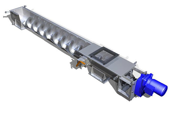
Sludge Screw Conveyor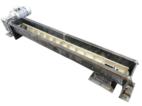
Garbage screw conveyor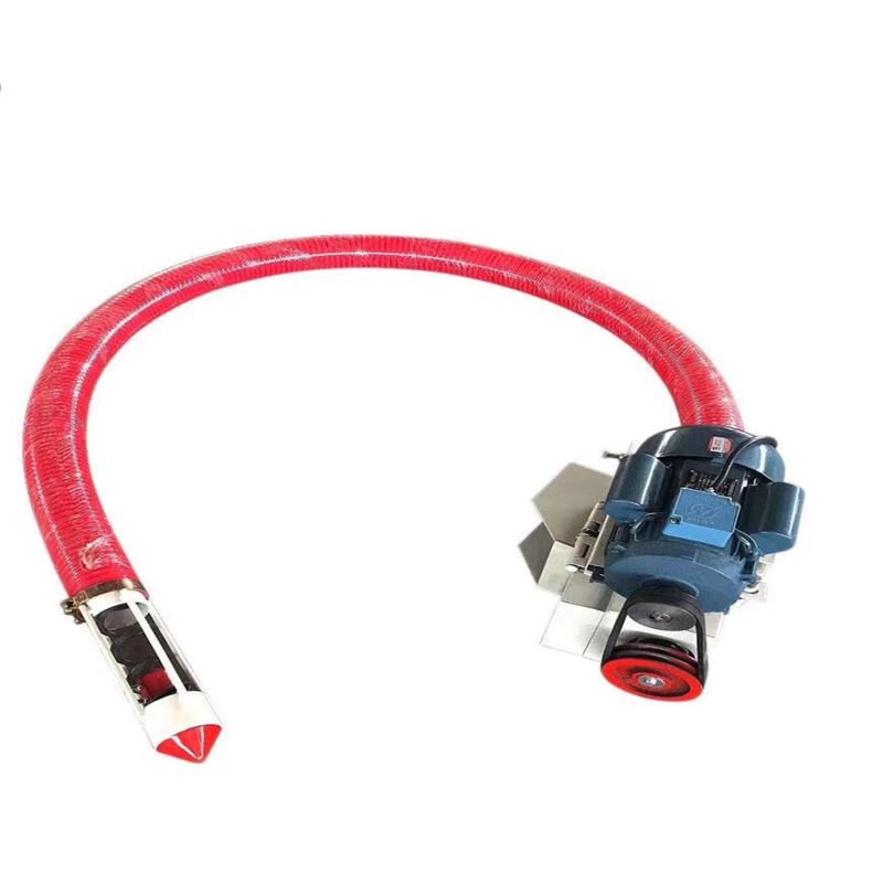
Flexible Feed Auger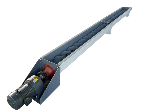
shaftless screw conveyor