Tubular vs U-Trough Screw Conveyor: Look at These 3 Differences
Saturday July-18 2026 16:11:04
When designing a factory material handling system, choosing the wrong screw conveyor casing type can easily lead to powder spillage, material jamming, or cross-contamination, which directly increases equipment maintenance downtime. Tubular and U-Trough screw conveyors have fundamental structural differences. Simply put, if you need a conveying inclination angle above 15° or if the material is volatile and toxic, you should choose a tubular type; whereas, if frequent washing is required, cohesive materials are handled, and the operation is horizontal, the U-trough type is a more cost-effective choice for daily operation.
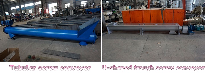
Specifications and Application Indicators Quick Reference Table
| Comparison Dimension | Tubular Screw Conveyor | U-Trough Screw Conveyor |
| Sealing & Pressure Capacity | Fully enclosed tubular structure, capable of withstanding slight positive or negative pressure pneumatic airflows. | Top cover fixed by bolts or toggles, only preventing gravity-drop dust. |
| Operating Inclination Angle | 0° to 90° (capable of vertical conveying). | 0° to 15° (conveying capacity drops sharply when exceeding 15°). |
| Equipment Cleaning Method | Relies on flanges at both ends or external CIP injection pipelines for flushing. | Removable top cover, allowing full-length open-access direct brushing. |
| Multi-point Inlet/Outlet Configuration | The number of inlets and outlets is restricted by the casing opening which reduces structural strength. | Supports multiple pneumatic or manual discharge gates at any position along the line. |
3 Technical Differences Determining Operating Cost and Lifespan
Difference 1: Sealing and Environmental Compliance
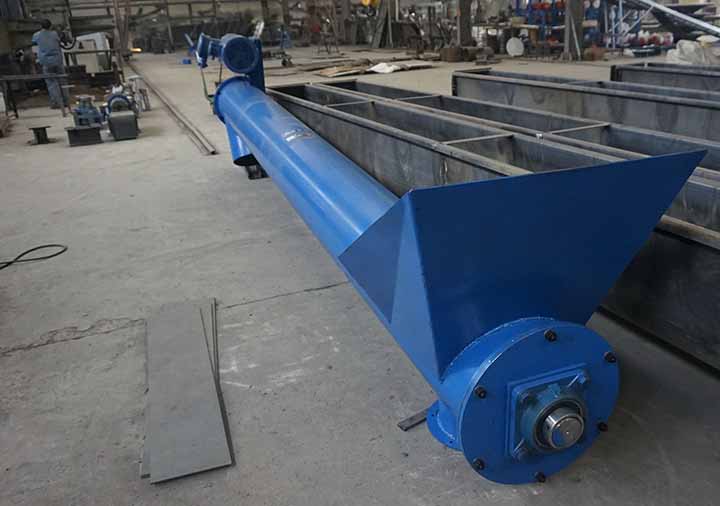
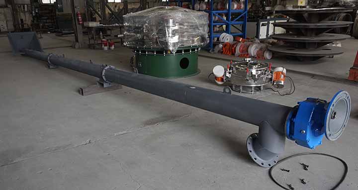
The tubular screw conveyor utilizes a seamless steel pipe as the housing, equipped with packing seals or mechanical seal assemblies at both ends. This structure completely blocks ultra-fine powders (such as carbon black or fly ash with a particle size under 50 microns) from leaking outward and can withstand slight positive pressure within 0.05MPa, preventing dust from entering the workshop environment.
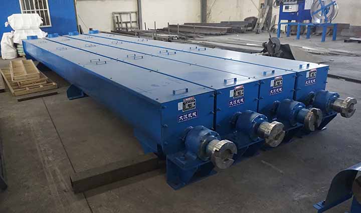
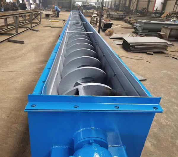
In contrast, the casing of a U-trough is made of bent steel plates with a removable cover on top. Although rubber strips can be installed along the edges of the cover, fine dust still seeps out from the cover joints when facing airflow impacts or positive pressure conveying. Therefore, under working conditions requiring strict dust control, the tubular structure shows a clear physical barrier advantage.
Difference 2: Material Residue and Daily Cleaning Cost
The U-trough screw conveyor offers extreme convenience during maintenance. Operators can remove the entire length of the cover simply by unfastening the toggles, leaving the clearance between the screw shaft and the bottom of the trough clearly visible for direct washing with high-pressure water guns or scraping with scrapers. This blocks any possibility of cross-contamination between different batches of materials.
The interior wall of a tubular conveyor is a blind zone. Since the tube body cannot be disassembled along its full length, if it is used to convey materials containing moisture or high viscosity, the material layer generated between the outer edge of the screw flight and the inner tube wall will cake and harden. Cleaning the inside of a tubular type typically requires pulling out the entire screw shaft or setting up dedicated chemical cleaning solution circulation lines, which raises daily cleaning labor and time costs.
Difference 3: Gravity Space and Limits of Conveying Inclination
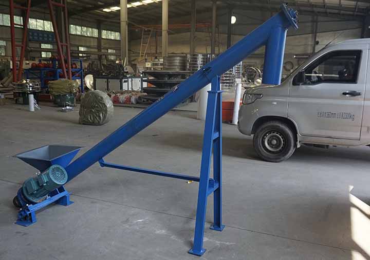
As the conveying inclination angle increases, the material slides downward in the clearance between the screw flight and the casing due to gravity, forming backflow. Because the upper space of the U-trough conveyor is wide, when the inclination angle exceeds 15°, the backflow amount reaches more than 30% of the total conveying volume, and the motor power is mostly consumed by the internal friction of the material.
The tubular conveyor restricts the lateral scattering space of the material. The tube wall exerts a continuous frictional resistance on the material, forcing it to advance upward along with the flights. Even in a 45° or even 90° vertical lifting state, the tubular conveyor can still maintain a constant advancing efficiency, which provides a feasible solution for production line designs with tight factory floor space requiring compact space layouts.
How to Choose Based on Actual Working Conditions?
To avoid blind selection leading to late-stage retrofitting, please perform a checklist inspection according to the following physical parameters and working condition indicators:
If your working condition meets the following conditions, choose Tubular:
- Inclination angle ≥ 15°: The material needs to be conveyed at a high angle or even lifted vertically to the top of a silo.
- Dust particle size ≤ 100 μm and hazardous: The material is flammable, explosive, or has an irritating odor, and is not allowed to contact the workshop air.
- Outdoor open-air placement: The equipment is arranged in an outdoor environment without a rain shed, requiring the shell to have the ability to prevent water and windblown sand intrusion.
If your working condition meets the following conditions, choose U-Trough:
- Material moisture content ≥ 8% and sticky: The material easily adheres to the shaft center, requiring manual scraping by opening the casing weekly or even daily.
- Single conveying line requires multi-point discharging: The production line below is equipped with multiple batching scales or downstream processing equipment, requiring 2 or more discharge outlets in the middle of the conveyor.
- Material contains large granular lumps: The material particle size is larger than 20 mm, which may cause jamming during conveying, requiring convenient access to open the cover at any time for manual troubleshooting.
3D CAD Dimensioning and Non-standard Customization
Material bulk densities (ranging from 0.2 t/m³ for lightweight wood chips to 3.5 t/m³ for iron ore concentrate) and abrasiveness vary wildly across different industries. Standard model parameters cannot be blindly copied into all production lines. We can generate customized equipment drawings using 3D software based on the physical characteristic parameters of the material, the conveying tonnage per hour, and the specific installation space drawings provided by the user.
In customized solutions, dedicated disassembly slide rails can be configured for the tubular structure, allowing a single person to pull out the inner shaft easily; for the U-trough type, quick-opening clamp covers and replaceable wear-resistant liners can be provided, reducing the overall operating and consumables costs of the factory right from the design source.
Frequently Asked Questions
Q: How can a tubular conveyor achieve quick clearing during material blockages without disassembling the tube body?
A: This requires adding physical components during the design stage. Typically, quick-opening clean-out handholes (usually 150mm × 150mm rectangular holes) with sealing gaskets are installed at the bottom of the tube body close to the flange joints. When a blockage occurs, shut down and disconnect the power, open the handhole bolts, and you can pull out the accumulated material inside with a clean-out rod without dismantling the several-meters-long steel pipe as a whole.
Q: Why is the cost of replacing the liner of a U-trough more cost-effective than a tubular type when handling highly abrasive materials?
A: When conveying highly abrasive materials such as quartz sand and slag, the bottom of the casing suffers severe scraping. The U-trough structure allows a layer of ultra-high molecular weight polyethylene or wear-resistant steel liner to be bolted to its bottom; when worn out, you only need to open the top cover and remove the bolts for local replacement. Conversely, once the inner wall of a tubular conveyor is worn through, it usually requires cutting and replacing the entire section of seamless steel pipe, or sending the whole tube back to the factory to reline the wear-resistant layer, making the material and downtime costs much higher than those of a U-trough.
Q: Can a U-trough with sealing gaskets completely replace a tubular type?
A: No. The U-trough casing is welded from bent thin plates, and its cross-section is geometrically asymmetric, which dictates that it cannot withstand internal gas pressure. Even if high-elasticity sealing strips are installed at the cover plate, once there is pneumatic conveying feeding at the front end of the conveying line, or an internal gas pressure accumulation above 0.01MPa occurs, the airflow will find weak points to blow open the gaskets, causing dust to gush out. The tubular type, due to its cylindrical physical pressure-resistant structure, has a stability under such working conditions that cannot be replaced by a U-trough.
Conclusion
Tubular screw conveyors and U-trough screw conveyors each have their specific application boundaries. The tubular type relies on its fully enclosed design and high-inclination advancing capability to solve the challenges of hazardous dust leakage and vertical space lifting; while the U-trough type, by virtue of its full-length open physical construction, offers a lower maintenance threshold in horizontal high-viscosity material conveying, frequent cleaning, and wear part replacement. When selecting a model, factories need to comprehensively evaluate rigid data such as material particle size, viscosity, conveying angle, and factory height to determine a conveying solution that conforms to economic benefits.
Sugested Products
Heavy Duty U-Trough Screw Conveyor for Bulk Material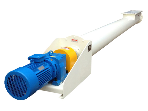
Tubular Screw Conveyor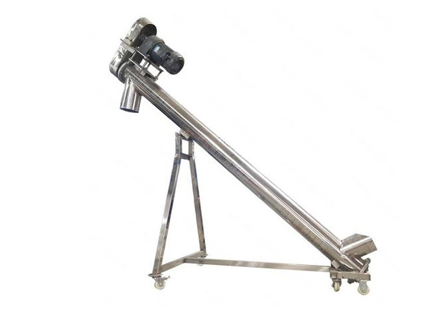
Inclined Auger Conveyor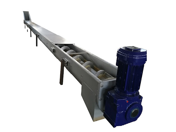
Household waste screw conveyor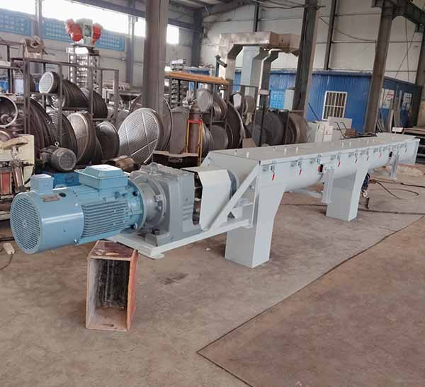
Poultry Litter Auger Conveyor