Horizontal vs. Vertical Auger Conveyor: How to Choose the Right One for Your Plant
Friday July-31 2026 13:32:29
An auger conveyor utilizes rotating helical screw blades within a pipe or trough to generate axial thrust, pushing bulk materials along a fixed path. In industrial contexts, "screw conveyor" and "auger conveyor" refer to the exact same mechanical equipment, with naming differences stemming from industry habits: heavy industry and mining prefer "screw conveyor," while agriculture, powder processing, and grain machinery typically use "auger conveyor." This equipment is commonly used for transporting powdered, granular, and small block materials, maintaining continuous material movement through fixed clearances between metallic components and the screw shaft.
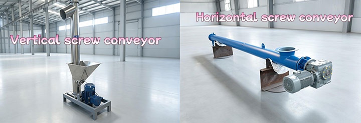
Quick Comparison: Horizontal vs. Vertical Auger Conveyor
| Comparison Dimension | Horizontal Auger Conveyor | Vertical Auger Conveyor |
| Installation Angle | 0°–20° (Horizontal) to 60° (Inclined) | 60°–90° (Vertical Lifting) |
| Footprint | Extends horizontally along the floor, requiring long longitudinal space | Occupies minimal drive and inlet area at the base, extending vertically upward |
| Lifting Height | Suitable for long-distance horizontal transfer; limited vertical lift height | Directly lifts materials to high-level silos of 10–30 meters |
| Feeding Method | Relies on gravity for natural falling; unpressurized feeding | Requires a forced feeding device or horizontal pressure screw feeder |
| Operating Speed | Low-speed operation (typically 40–120 rpm) | High-speed operation (typically 200–500 rpm, relying on centrifugal force) |
| Maintenance Focus | Intermediate hanger bearings and discharge blockages | Bottom thrust bearing, top hanger bearing, and wear bushings |
Deep Dive into Horizontal Auger Conveyors
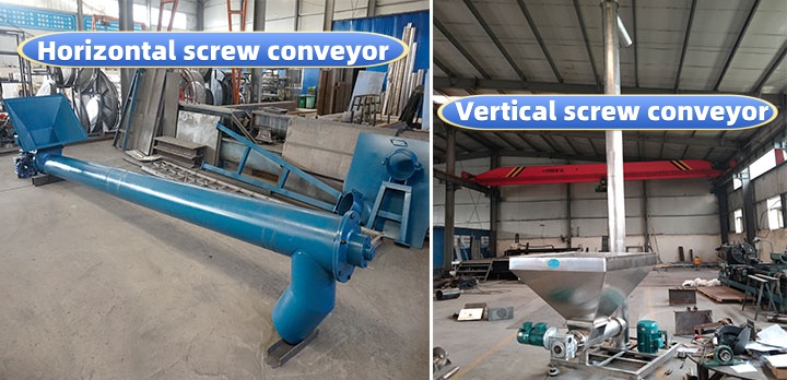
Horizontal Screw Conveyor use a low-speed rotating screw shaft to generate thrust. Under the action of gravity and trough wall friction, materials move forward along the bottom rather than rotating with the blades. This operating mechanism causes minimal damage to material particle structures and generates low friction heat.
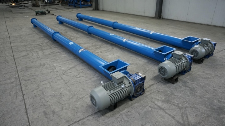
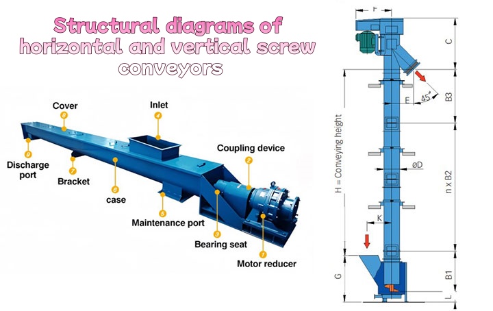
In terms of structural configuration, when the conveying distance exceeds 4–6 meters, intermediate hanger bearings must be installed to support the screw shaft and prevent sagging or casing scraping. Horizontal configurations with multiple discharge ports can be controlled via pneumatic valves to distribute materials into reactors, mixers, or storage bins arranged below. Since the blade thrust acts directly in the direction of horizontal displacement, power consumption for horizontal transfer is relatively economical.
Deep Dive into Vertical Auger Conveyors & Lifting Systems
Vertical Auger Conveyor lifting systems elevate materials vertically at right angles. The internal screw shaft requires a high rotation speed to generate centrifugal force, pressing materials against the inner casing wall. The resulting wall friction prevents materials from rotating together with the blades, driving them upward along the helical surface.
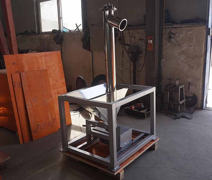
By relying entirely on centrifugal force and thrust to overcome gravity, vertical lifting systems complete high-level feeding within minimal floor space. The top of the unit is equipped with a thrust bearing housing to bear the self-weight of the entire screw shaft and the reverse axial force generated during material ascent. The suspended casing pipe is secured by an external steel structural frame, reducing floor space occupation.
Process Integration & Feeding Solutions
Vertical auger conveyors cannot draw in materials automatically via gravity. If bulk materials accumulate directly at the vertical inlet, high-speed rotating blades will sling materials outward, leading to inlet clogging or feed interruption. Therefore, process integration requires matching feeding solutions:
Forced Pressure Screw Feeder: A horizontal short screw is connected to the bottom of the vertical pipe to push materials into the bottom inlet under constant pressure, achieving continuous filling.
Bottom Hopper: Serving as a material buffer, the hopper contains internal mixing paddles or an auxiliary flight to eliminate bridging and provide a steady supply stream to the vertical screw.
In complete production line layouts, the outlet of upstream bulk bag unloaders or grinders connects to the hopper via flexible joints, and the vertical elevator delivers materials to the top, discharging directly into downstream high-level weighing bins to close the automated processing loop.
4 Key Factors to Choose the Right One for Your Plant
During selection, plant layout and material characteristics dictate structural choices:
Plant Spatial Layout and Floor Limitations: When floor equipment is dense and inclined lines cannot be arranged, vertical lifting systems utilize high-altitude vertical space; if the plant offers long straight passages, horizontal structures provide better accessibility for installation and maintenance.
Conveying Distance and Elevation Requirements: For horizontal transfer exceeding 10 meters without elevation needs, choose a horizontal screw. To transport materials directly to reaction bin tops three stories high, a vertical screw or a "horizontal + vertical combined system" is appropriate.
Material Abrasiveness and Friability: High speeds in vertical systems increase collisions between materials and casing walls. Friable particles (e.g., catalyst pellets, extruded granules) are prone to breakage during elevation. Highly abrasive or heat-sensitive materials are better suited for low-speed horizontal pipelines.
Long-Term Maintenance and Wear Costs: Bearings on horizontal equipment are mostly located externally at both ends, making lubrication and replacement straightforward. Due to high speeds and heavy bottom-bearing loads, vertical equipment requires scheduled inspection and replacement plans for seals and bushings.
Cost Comparison
The total investment should be evaluated over the entire service life rather than comparing equipment prices alone. A horizontal auger conveyor often requires fewer supporting structures for floor-level conveying, while a vertical system may include additional components such as a feeding screw, support frame, and elevated maintenance access. During operation, routine expenses are influenced by bearing replacement, lubrication intervals, wear parts, and shutdown time. Reviewing both initial investment and long-term maintenance requirements before purchasing helps match the conveyor configuration with the production layout.
Real Project Case
A customer producing mineral powder needed to transport material from ground-level storage to a mixing system installed approximately 8 meters above the floor. Instead of using a long inclined conveyor, the conveying line was arranged with a short horizontal screw feeding a vertical auger conveyor. This layout reduced the horizontal routing distance and simplified equipment installation around existing production machinery. After commissioning, daily inspection focused on the drive unit, inlet hopper, and lower bearing assembly, allowing maintenance work to be completed without dismantling adjacent equipment.
Decision Tree for Equipment Selection
Choosing the right auger conveyor starts with the conveying route rather than the equipment model.
| Selection Condition | Recommended Solution |
| Need horizontal transfer only? | Select a horizontal auger conveyor. |
| Need to lift material to an upper floor or silo? | Select a vertical auger conveyor with a pressure feeder. |
| Need both horizontal conveying and vertical lifting? | Combine horizontal and vertical conveyors into one conveying line. |
| Material is fragile or sensitive to particle breakage? | Evaluate whether a low-speed horizontal conveyor or another conveying method is more suitable. |
Technical Specifications
Technical specifications should be determined according to material properties and production requirements instead of selecting standard dimensions directly. Screw diameter, shaft speed, pitch, casing structure, motor output, inlet arrangement, and discharge configuration all influence conveying performance.
| Parameter | Horizontal Auger Conveyor | Vertical Auger Conveyor |
| Screw Diameter | 100–600 mm | 100–500 mm |
| Conveying Length | Up to 40 m (single unit) | Typical lifting height: 3–30 m |
| Installation Angle | 0°–20° (up to 60° for inclined models) | 60°–90° |
| Screw Speed | 40–120 rpm | 200–500 rpm |
| Feeding Method | Gravity feeding | Pressure screw feeder or hopper |
| Drive Position | Head or tail drive | Bottom drive |
| Typical Materials | Powder, granules, small bulk solids | Powder, granules, free-flowing materials |
| Maintenance Focus | Hanger bearings and screw flights | Bottom bearing, bushings and thrust bearing |
Frequently Asked Questions
Q1: What is the difference between a screw conveyor and an auger conveyor?
In technical standards and mechanical structure, both are identical, consisting of a screw shaft, casing, drive unit, and bearings. In terms of naming conventions, chemical and metallurgical sectors commonly use "screw conveyor," whereas plastic granule, grain/oil processing, and powder handling industries prefer "auger conveyor."
Q2: Can a vertical auger lifting system handle fragile materials?
Not recommended. Vertical lifting systems rely on speeds of 200–500 rpm to generate centrifugal force. Granular materials experience intense friction and impacts against casing walls and blades during high-speed rotation, making them susceptible to breakage. For friable materials, low-speed inclined horizontal screws or bucket elevators are preferred.
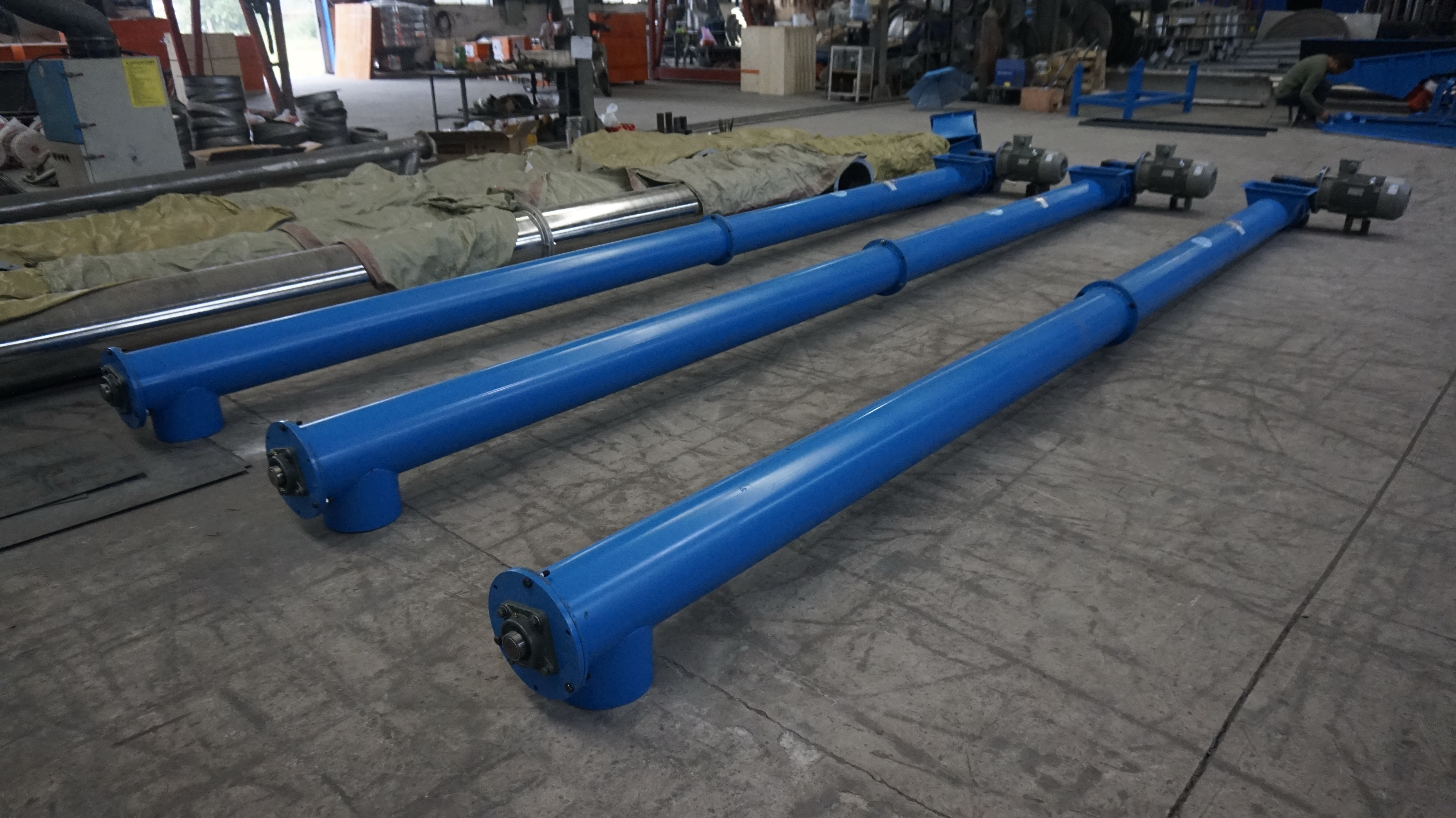
Choosing between a horizontal or vertical auger conveyor depends on practical plant spatial dimensions and material transfer paths. Horizontal equipment excels in low-speed operation, smooth conveying, and multi-point discharge, making it suitable for plant layouts extending along a flat plane. Vertical lifting systems resolve high-level feeding challenges within a minimal footprint but require proper forced-feeding designs for support. Matching material particle size, rheological properties, and plant CAD layout drawings forms the foundation for successful equipment selection and system integration.
Sugested Products
Cleated Belt Conveyor Machine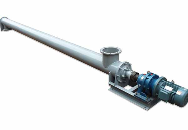
Dust Free Screw Conveyor Machine Manufacturer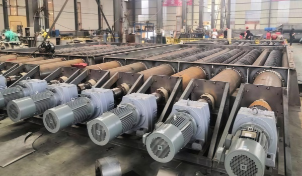
Live Bottom Screw Conveyor Machine Manufacturer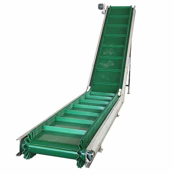
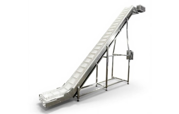
High Incline Sidewall Belt Conveyor Manufacturer