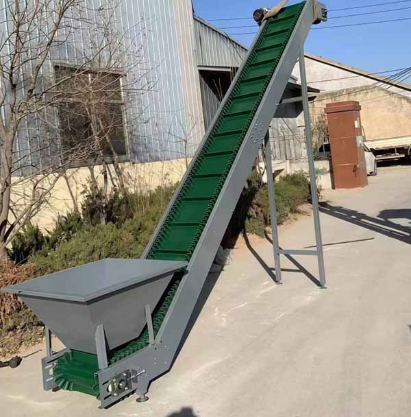
Steep Incline Conveyor System
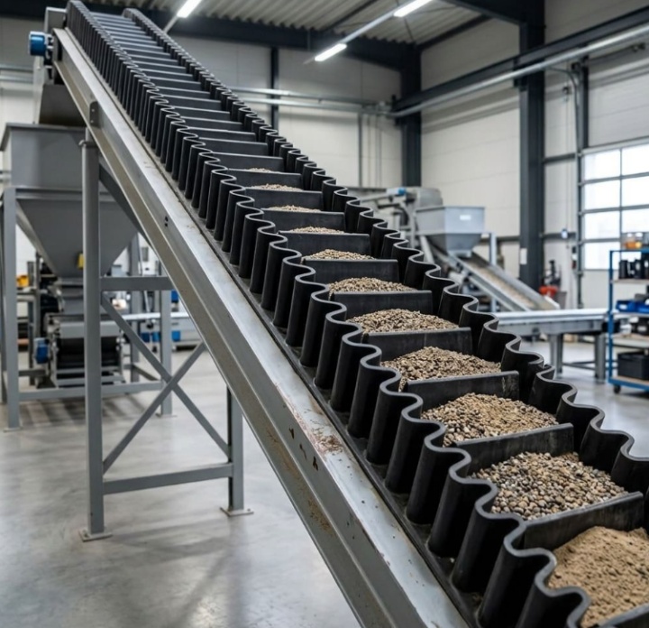
Unlike standard flat belt conveyors, which are limited to inclines below 18° to prevent material rollback, the Steep Incline Conveyor System utilizes corrugated sidewalls and transverse cleats to create pocket-style carrying spaces, enabling continuous elevation and vertical material transport at inclines ranging from 18° to 90°.
• Max Incline Angle: Up to 90° (Vertical Transport)
• Capacity Range: 50 m³/h – 3,000 m³/h
• System Layouts: Straight Incline, L-Shape, Z-Shape (S-Profile)
• Belt Width: 500 mm – 2000 mm
• Material Bulk Size: 0 mm – 400 mm
Steep Incline Conveyor System vs. Standard Incline Conveyor
| Comparison Dimension | Standard Incline Conveyor | Steep Incline Conveyor System |
| Max Angle | 12° – 18° (Limited by material friction angle) | 18° – 90° (Continuous vertical lifting) |
| Footprint / Space Requirement | Requires extensive horizontal span, consuming large plant ground space | Reduces horizontal projection length by 60%–70%, saving ground space |
| Material Rollback Risk | High risk of particle slippage and spillage when angle exceeds 18° | Corrugated edges and cleats form closed pockets with no material rollback |
| Equipment Combination | Requires multi-unit series connection: "flat belt + transfer tower + bucket elevator" | Utilizes a single integrated unit in Z-shape or L-shape layout, eliminating intermediate transfer points |
| Investment Cost | Involves high civil foundation construction and transfer tower framing expenses | Reduces transfer point civil engineering costs and lowers system maintenance and spare parts replacement expenses |
System Configuration: Horizontal-to-Incline Transitions
The structural characteristic of the Steep Incline Conveyor System lies in its continuous "horizontal loading → steep inclined lifting → horizontal discharge" integrated routing layout, primarily divided into L-shape and Z-shape (S-Profile) configurations. The L-shape layout comprises a bottom horizontal loading section followed by a steep incline lifting section; the Z-shape layout adds a top horizontal discharge section to the steep incline portion. Materials fall smoothly into the belt pockets along the bottom horizontal section, pass through the curved transition zone through the incline, and discharge smoothly upon reaching the top. This continuous operating mode replaces the cumbersome three-stage combination of flat belt feeding, transfer bucket elevator lifting, and flat belt receiving/distribution, eliminating drop height at transfer points while preventing material accumulation, caking, and dust dispersion at hopper chutes.
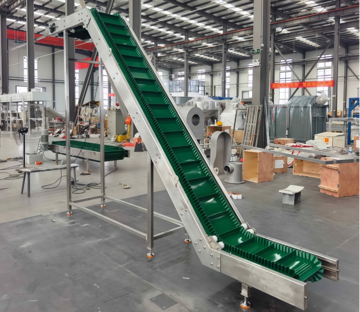
Key Components of Heavy-Duty Steep Incline Systems
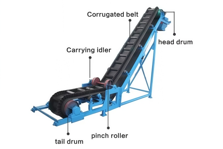
• Cross-Rigid Base Belt: Embedded with high-tensile polyester/nylon fabric layers or cross-reinforced steel cord layers, providing high bending resistance when passing over transition deflection wheels and drive drums to prevent transverse sagging under high longitudinal tension.
• Corrugated Sidewalls & Cleats: Flexible corrugated rubber vertical borders bend without generating internal stress; transverse cleats are fastened to the center of the base belt via bolts and thermal vulcanization, forming enclosed pocket spaces with the sidewalls on both sides.
• Deflection / Hold-Down Wheels: Installed in the convex bend zone transitioning from horizontal to steep incline, pressing against the borderless edges on both sides of the belt to prevent the base belt from lifting off the track under high tension.
• Self-Cleaning Tail Pulleys: Featuring squirrel-cage or spiral-cone structures, these pulleys push dropped materials outward, preventing bulk particles from entering between the pulley and belt to cause scratches or surface indentation.
Engineering Selection & Angle Calculation Guidelines
Capacity calculation for steep incline conveyor systems must account for the pocket filling rate attenuation under varying angles. The theoretical volumetric capacity formula is as follows:
Q = 3600 · A · v · ρ · k
• Q: Theoretical mass conveying capacity (t/h)
• A: Cross-sectional area of a single pocket formed by cleats and sidewalls (m²)
• v: Operating belt speed (m/s, recommended range 1.0 - 2.5 m/s)
• ρ: Bulk material density (t/m³)
• k: Incline filling coefficient (k ≈ 0.85 for 30° - 45°; k ≈ 0.75 for 45° - 75°; k ≈ 0.65 - 0.70 for 90° vertical lifting)
During selection, cleat spacing must be set greater than 2 times the maximum particle size limit of bulk materials, and the bend radius at transition zones must exceed 1200 mm to prevent high stress concentration from damaging internal cords.
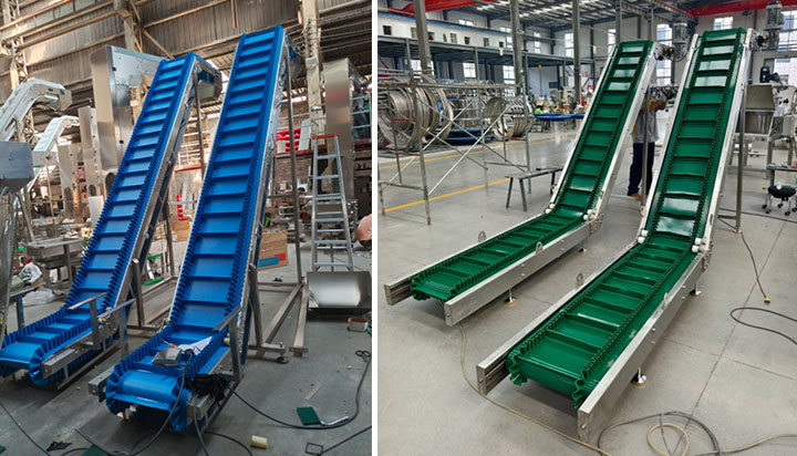
Technical Specifications & Incline-to-Capacity Matrix
| Belt Width (mm) | Sidewall Height (mm) | Cleat Profile | Max Lump Size (mm) | 30° Incline Capacity (m³/h) | 60° Incline Capacity (m³/h) | 90° Vertical Capacity (m³/h) |
| 500 | 120 – 160 | Type T / Type C | ≤ 50 | 120 | 100 | 85 |
| 800 | 160 – 200 | Type TC / Type TCS | ≤ 100 | 350 | 290 | 250 |
| 1000 | 200 – 300 | Type TC / Type TCS | ≤ 160 | 650 | 540 | 460 |
| 1200 | 300 – 400 | Type TCS | ≤ 220 | 1100 | 920 | 780 |
| 1600 | 400 – 500 | Type TCS (Reinforced) | ≤ 300 | 2000 | 1650 | 1400 |
Custom Engineering Options: Hoppers, Cleats & Portability
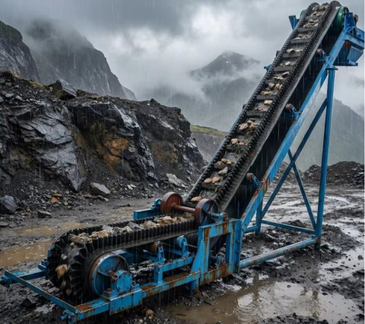
To adapt to diverse plant working conditions, the system provides custom configuration extensions. At the loading end, an incline conveyor with hopper system can be configured; the internal hopper is fitted with wear liners and impact idlers to absorb kinetic drop energy while guiding materials evenly into cleat pockets. For cleat selection, various cleat profiles (T, TC, TCS) are available: Type T is suitable for small particle bulk materials under 40°; Type TC and TCS feature inclined support ribs engineered for large-lump heavy-duty conditions above 45° to resist material pushing forces. For stockyards and temporary mining operations, the system can be configured with a mobile base featuring heavy-duty hydraulic tires and outriggers for fast on-site mobility and angle adjustment.
Technical FAQ Section
Q1: What is a steep incline conveyor system?
A: A steep incline conveyor system is a class of conveying equipment designed for continuous transport of bulk materials under steep incline conditions (18° to 90°). Through the combination of cross-rigid base belts, flexible corrugated sidewalls, transverse cleats, and deflection wheels, it achieves steep incline or vertical elevation without material rollback.
Q3: Can you use a cleated incline conveyor instead of a standard belt conveyor?
A: In working conditions where the conveying route is constrained by plant space and the incline angle exceeds 18°, a cleated incline conveyor can be utilized in place of a standard flat belt conveyor. The cleats block materials from sliding down the slope, keeping stable conveying volume while shortening transport distances.
Q3: What is the main difference between an incline conveyor and a standard belt conveyor?
A: The primary difference lies in the material carrying method and operating incline angle. A standard belt conveyor relies solely on friction between the material and belt surface, limiting incline angles to under 18°. An incline conveyor system leverages transverse cleats and sidewalls fixed to the belt surface to create mechanical pockets, relying on physical support to lift materials to higher angles or even 90° vertical heights.
Summary
The Steep Incline Conveyor System relies on the structural combination of cross-rigid base belts, corrugated sidewalls, and high-tensile cleats to overcome the bottleneck where traditional belt conveyors cannot lift at steep angles due to material friction limits. Its Z-shape and L-shape layouts integrate horizontal loading, steep lifting, and horizontal discharge into a single seamlessly connected unit, eliminating transfer tower construction expenses and intermediate drop wear. By accurately calculating the incline filling coefficient k and selecting matching cleat profiles (T/TC/TCS) with hopper-fed bases, this system demonstrates engineering value in reducing plant footprint spans and improving vertical turnover capacity across mining, quarrying, and bulk terminal applications.
Sugested Products
Aggregate belt conveyor system
Portable belt conveyor system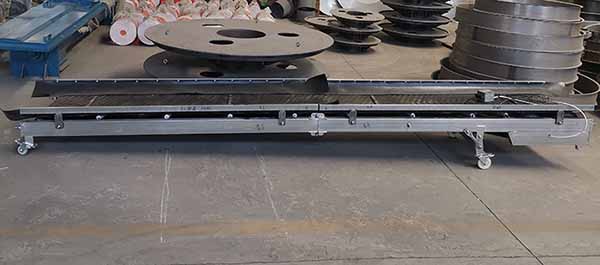
Scrap metal belt conveyor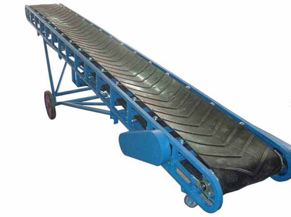
Iron ore belt conveyor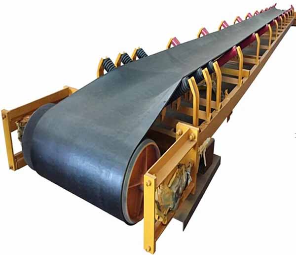
heavy duty belt conveyor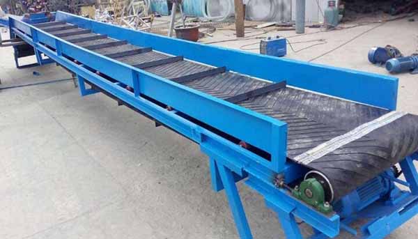
Gypsum belt conveyor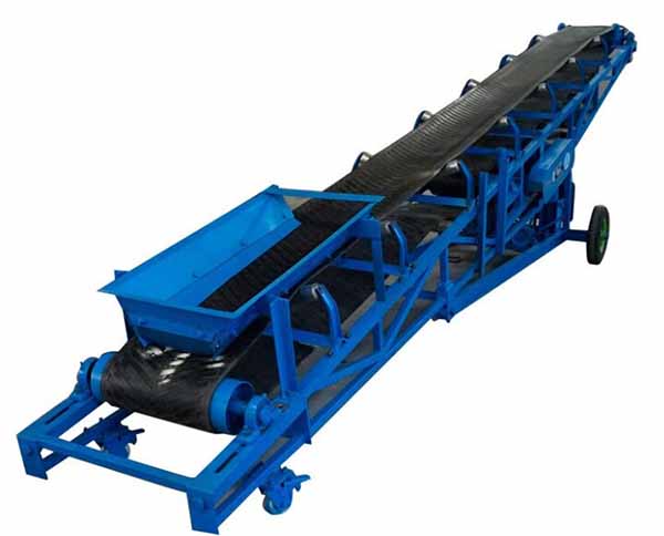
Bauxite belt conveyor